Changing of the Guard: How LTE Replaced Wi-Fi & WiMAX
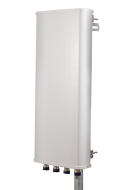
As technology improves and shifts to new standards, so must the products that propagate them. In the WISP world, LTE antennas are becoming the new standard as older and slower technologies such as Wi-Fi and WiMAX antennas slowly get phased out. This progression is inevitable as customers demand faster data rates, more bandwidth and greater coverage.

What’s So Special About LTE, Anyway?
The main reason why LTE (Long Term Evolution) antennas differ from those you see in current WiFi and WiMAX deployments has to do with interference. Whereas the 802.11 protocol establishes minimum SINR (signal to interference plus noise ratio) to achieve a modulation or data rate, 802.11 devices can detect co-channel interference bursts when they occur and respond dynamically by dropping the modulation to enable data transmissions, albeit at lower data rates. The SINR level is attributed to both intra- and inter-cell interference.
While there are several variants of LTE (also known as 4G) currently being used, most networks today are relying on a variety of frequency division duplex (FDD) or time division duplex (TDD) orthogonal-frequency division multiplexing (OFDM) modulation solutions to achieve high data rates. While FDD/TDD OFDM is efficient in modulating data and negating the impact of intra-cell interference, it is highly susceptible to self- and inter-cell interference, particularly when handling high traffic volumes. This interference is better characterized by the carrier to interference noise ratio (CINR). Despite the release of several interference coordination technologies in LTE, inter-cell interference is still one of the biggest factors of quality degradation, particularly for devices near the cell edges. This is a serious issue in LTE deployments that maximize spectral efficiency and use the same or limited number of channels over adjacent sectors and cells. In LTE, a lowering of CINR can reduce transmission speed and throughput and, in some cases, cripple communication altogether — negating the reason for using LTE in the first place.
For this reason, special care and planning is needed to prevent interference from impacting data transmissions over LTE networks. Some of the most effective ways to prevent interference include:
Strict attenuation: Radiation sprawl is one of the biggest causes of interference in LTE networks. You can prevent sprawl by using base station antennas that radiate energy only where it is needed. Ideally, you should be using antennas that have a sharp pattern attenuation outside of their 3 dB beamwidth, as well as high front to back ratios and low side lobe levels.
Fixed electrical downtilt: Interference between sites can be reduced through electrical and mechanical downtilt, which involves directing radiation toward the ground instead of toward the horizon. By doing this, you can prevent your signal from being picked up by an adjacent site. Keep in mind, though, that large degrees of mechanical downtilt can flatten your radiation pattern, increasing its front-to-back and side lobes. It is therefore recommended that you use an antenna with a combination of fixed electrical and mechanical downtilt. Electrical downtilt eliminates pattern flattening, and you can add mechanical downtilt on top if it is required. With electrical downtilt, signals are directed downward by shifting the antenna’s interior electrical mechanisms; with mechanical downtilt, you must physically adjust the angle of the antenna.
45° Polarization: As opposed to the standard horizontal and vertical polarization used in WiFi and WiMax, the Third Generation Partnership Project (3GPP) recommends a polarization of ±45° for LTE. This is because the received signal at the base station is typically elliptical after propagating over the surrounding terrain. By slanting the electrical field to 45°, you can equalize the received signal level in both chains, reduce interference and improve coverage and performance.
Half inch coax cables: LTE is susceptible to passive intermodulation (PIM), which can come from multiple sources in your RF chain. While PIM-testing equipment may be required to locate specific sources of PIM (i.e., a filter, power amplifier, surge protector, faulty cable), there are some obvious sources that can be more easily addressed. PIM originates from RF arcing in metal-on-metal contact over microscopic distances, so the first step to reducing PIM is to use the right cables and connectors. LMR cable has low PIM characteristics because it has a braded outer conductor. Solid, ½ inch coax conductors are preferred, with N-type and SMA connectors. However, they can have PIM issues if improperly torqued due to their smaller size and limited contact areas. 4.3-10 or 7/16 DIN connectors offer larger contact areas and are generally rated at a higher PIM specification. Right now, the LTE WISP industry requires a -150 dBc at 2x20W. You can expect the WISP industry to push for even more stringent PIM levels looking forward.
Author:
Justin Pollock, Ph.D.
Antenna Engineer
KP Performance Antennas

